I call this one the Pipe Stretcher. It is a combination of the best
elements of what I have built in the past combined with improvements
that I felt some of my other designs where lacking. I worked on it with
the mindset of it being the last design I may ever make, so it probably
is my swan song in the DIY extender game, as I have reached the goals I
had hoped to for length and just don’t
PE
for length any longer. In a nutshell, this is my best attempt to design
a easy to build a quality extender from materials you can find at most
home building stores. I’ve put a lot of work into documenting the
creation process with words as well as pictures because I do not know
how quickly I will be able to respond to individual questions. Life has
been a struggle lately… but I digress. To the Pipe Stretcher!
It
makes use of a “quick noose” system that I have used in past designs.
Yes it’s a noose, but it’s not a traditional noose, don’t worry, we will
get in to that later. Unlike commercial extenders, this extender is not
intended in any way to be hidden beneath clothing. That is for two
reasons, one, I believe
PE should
be closely monitored at all times and secondly, due to the do it
yourself nature of the project, easy to find and easy to build with
materials can’t compete with custom molded plastic parts for size
resulting in a larger end result. That, and nothing in my wardrobe could
conceal even the smallest sized extender so I scratched that off the list of things to worry about years ago.
Below
is the construction tutorial, followed by the calibration, sizing and
use of the device. Sorry, I do not have a budget price of what it will
cost since I had a lot of the materials around from other projects but I
purchased everything I used from the Home Depot, and most of the
materials are found in the plumbing section.
The biggest improvements from previous designs are:
- The springs have been completely hidden.
- The noose more easily removes/attaches for initial sizing, cleaning, or replacement.
- Wider, more comfortable base.
- The base is now made from easier to find fittings.
- The alternate head configuration allows for a much greater range of sizes.
- Looks cooler.
Look close at the plans and images, they probably describe things better than my words ever could. Good luck!
:)
Materials
These
are the materials I used, mostly because it is what I had on hand or
access to. I did my best to make use of materials that are fairly easy
to find at your local hardware store but there very well may be better
alternatives out there.
- 6 - 1/2” PVC 90degree elbows
- 2 - 1/2” PVC Caps
- 1/2” PVC pipe (12” length)
- 4 - Bi-fold closet door springs
- Chicago Screws - Enough to make two posts, both at least the same length as your BPEL (two “end” pieces and various extension pieces)
- 2 - Machine screws (same sized thread as Chicago screws 8/32”)
- Latex tubing (6” length) - for noose (shown in image is 3/8”, but I used 1/4” tubing in final as a personal preference)
- Rigid 3/8” tubing (12” length) Rigid enough to support springs and wide enough to slide over Chicago screw posts)
- Velcro tape (12” length) - Not sticky backed Velcro tape, but the kind with hooks on one side, fuzz on the other
- PVC Glue (or any glue that will bond to the plastic PVC)
- Black electrical tape
- Hot glue gun
- Various drill bits (just slightly larger than the materials they are matched up with in the picture)

Constructing the Base
Start
by cutting three pieces of the 1/2” PVC pipe 1.5” long. Apply glue to
the pieces and place them between two PVC 90s. Make sure they are
aligned squarely, and that the fittings butt up tight to each other. I
used a little extra glue so the gap between fittings could be filled in
by the dry glue and sanded nearly smooth later. Repeat this process for
two more C pieces for a total of three.
After the glue is set and
dry between the fittings, we will make some marks that will become the
posts. I used the seams on the fittings as guides to mark the same on
each side. Use a drill bit slightly larger than the machine screws and
drill top and bottom of both sides of one the C pieces. Ideally, you
want it as snug as possible, I actually drilled the bottom and used a
tap set to add threads to the upper holes, but being plastic, drilling a
small enough hole that you can just force the threads of the machine
screws through (by screwing them with a screwdriver) should work well if
you don’t have a proper 8/32” tap set. Using a larger bit, drill
halfway through the bottom holes to allow for countersinking the head of
the screw. Again, the bottom hole can, and should be just loose enough
to allow turning the screw, but certainly make the top holes as tight as
possible for stability of the posts later.
Wind the screws in and
cut them down if necessary so a Chicago screw extension can wind down
entirely onto it, effectively securing the bolt to the base on each
side.
Cut two more sections of 1/2” pipe about 1.5” long and push
them into the fitting ends of the base. I didn’t glue mine, just forced
them in securely. This will form the connection for the removable half
of the base. The only reason I didn’t glue them was since the half of
base uses friction to stay attached I worried that over time and
continued attaching and removing of the base the fittings might loosen,
at which point one could simply cut some fresh 1.5” long pieces to keep
the base in place.


Building the Head
Using
one of the two remaining C pieces, mark for holes where the posts will
fit through. As seen in the image, I eye-balled as best I could from
front, then from the back, and averaged the difference from the top, and
also used the seams on the fittings as guides. Using the drill bit that
is slightly larger than the Chicago screw extensions, making the holes
large enough to easily slide along the posts.
Next, drill the two
caps with holes large enough to easily fit over the rigid 3/8” tubing,
this will be your largest holes. Cut two pieces of the 1/2” PVC pipe
roughly 2.25” long. These will fit between the C piece and the caps and
conceal the posts and springs later on. In this configuration glue is
not necessary for these fittings, but you can use a small amount of glue
of your pieces don’t fit securely enough. For the alternate
configuration, glue will be required at this step, and the larger holes
will be on the C piece and the post sized holes will be drilled on the
two caps (I will discuss that in more detail later).

Sanding and Smoothing
I
made use of the seams in the fittings as guides for marking and
drilling holes but since the drilling is now done, we can file and sand
down everything as smooth as possible. The smoother the better. The
fittings can sometimes come with some pretty sharp edges so this is an
important step.
The Noose
Cut
the Velcro tape along the length of it at a width that will easily
thread into your choice of latex tubing, I used about a 7” length of
Velcro, and about a 5” length of latex tubing. This may take a try or
two because getting it through the tubing can be a struggle if it is a
little too wide. I used electrical tape along the length to protect the
latex tubing from the sharper edges of the Velcro tape.
If needed, use a small wire to fish the Velcro through the tubing.
Use
some of the remaining Velcro to create a connection pad on the head of
the extender. I did it fuzzy side out and secured it with a hot glue
gun. If you were looking at the extender head from the side like a
clock, I glued my pad between the 7:00 and 10:00 points


Assembly
To
assemble the extender, you will need to build your posts from Chicago
screws and slide on the head piece, two springs on each side, then the
2.25” pieces of pipe with caps on each (these may be glued together from
a previous step. either way, the springs should fit through the large
holes in the cap.
Now cut two pieces of the rigid 3/8” tubing
long enough so that when fully assembled, the tubing will keep the
springs within the pipe fitting enclosure. You can find this measurement
by attaching the posts to the base, and with the head piece assembled,
measure the length of post between the cap and the base, then add a few
millimeters.
The last step is to attach the noose, basically just
stick it on, Velcro to Velcro onto the pad we glued on earlier, hooks
side down onto the fuzzy pad. It will likely need some adjustment later,
but that is as easy as peeling it off and attaching it again.


Optional Solutions
A couple of options, or after thoughts…
A
small helper piece can be cut to hold the extender in a compressed
position to make putting it on easier. Compress the fully assembled
extender and measure the distance between the top of the rods and the
top of the compressed head of the extender. Then cut a piece of rigid
3/8” tubing to that length and cut a small section out of it lengthwise,
enough to make it easy to slip on and off the rods, but not too much
that is will pop off when under some tension.
The second image
shows some possible solutions a possible problem I’ve run into with the
aluminum Chicago screws and the springs. I have seen brass and other
material screws which would negate this issue, but I already had the
aluminium on hand so I used them. Friction of the head piece sliding up
and down the posts can create a fine dust which may or may not become an
issue. I found if the sanded fittings are too rough, they collect dirt
quite easily. Ideally, buffing the plastic after sanding or painting the
plastic with a paint that will bond to plastic might also be a good
idea. Shown are some options for protecting the rods from the friction. A
length of packing tape, carefully applied to the top portion of the
rods, or a correctly sized drinking straw may work to prevent the
friction as well. I have used the tape for now and seems to be working
ok.
The third image shows the alternate mode for the head piece.
Because of the way the springs are compressed, the standard design
allows up to a certain length and beyond but how close tou can get to
the base is limited by the considerable height of the head piece. The
alternate design allows the attachment area to be much closer to the
base. It is essentially just the standard head flipped upside down, same
materials, same lengths. Everything else will work the same using this
alternate configuration, with the exception of the rod length will need
to be longer, and the different sized holes that are drilled in the top
and bottom of the standard head will now need to be switched as well.
The caps will be drilled to accommodate the rods and what was the top of
the head in the standard mode will now need to be drilled to
accommodated 3/8” rigid tubing. Also, in standard mode, glue between the
C piece and the caps is not necessarily needed if the fitting fit
snugly, however in alternate mode the pieces will need to be glued.
Depending
how smooth the gap between fittings on the head is you may want to
place some tape along the point where the two fittings meet. I didn’t
require anything but a smooth vinyl or fabric tape might work well.
Completed Extender
There you have it, easy as that.
:-) Not too hard to build I hope.
Next step is calibrating the springs and sizing the noose.

Calibration of the Springs
Calibration
of the device is fairly simple. Once constructed, simply place the
device onto a typical bathroom or kitchen scale. Some digital scales
will calibrate themselves when you turn them on, so put the device on
first then turn on the scale so the scale reads zero with the device
sitting on it (otherwise, if you have an analog scale, remember the
weight it says the device is and subtract that number from your readings
later).
Push down on the head of the device, compressing the
springs, until the scale reads 1 pound. This is where you subtract the
weight of the device if necessary, so if you device read 0.2 lbs. when
you put it on the scale, push down on the extender until the scale reads
1.2 lbs. Using a marker, make a small mark on the 3/8” tubing at the
closest point you can to the head of the device. Then push the head
further down to 3 or 5 pounds and mark it again on the tubing. What we
are doing is creating a guide onto the tubing that will later tell us
how much force the springs are under by which line is closest to the
head.
The same could be done with a fishing or luggage scale. hook
the end of the scale to the head and pull the fishing scale down while
holding the base secure, marking the tubing as you go. Stacking free
weights of known values could also be another alternative way to gauge
the tension on the springs.

Sizing of the Noose and Rods
There
are two aspects to correctly sizing the device. First, is correctly
sizing the noose. Once it is sized correctly, it will not need to be
readjusted to use the device multiple times. Second, is sizing the rods
and 3/8” tubing to apply the desired amount of tension to accommodate
your individual length.
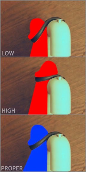
To size the noose look closely at the
attached images. The correct fit of the noose is designed to mimic the
way your hand holds in an OK grip making use of the curved surfaces of
the pipe to better spread out the force of the grip. A rigid non elastic
noose is required to mimic this effect. Using a noose that is too loose
will result in something reminiscent of a traditional extender noose
system, which is not ideal and not spoken highly of by many, it relies
too much on the narrow tubing and is uncomfortable applying any
reasonable amount of tension. Using a noose that is too tight is
obviously not ideal either.
The right sized noose will evenly
balance the head of the penis between the noose and the curved surface
of the device as shown in blue in the second image. It will take some
trial and error to get it right, you may need to shorten the Velcro (and
cut more of the latex tubing and tape away, etc.) that is why the
design makes use of Velcro for easy tweaking of the noose, but will hold
it securely once you commit to that fit.
The next step is to
size the rods so that the desired amount of force is applied while
wearing the device. This too may take some trial and error to get fit to
your individual size, but once you are in that range, it is easy to
move forward form there. Put the device on, or try to, it may be too big
or too small to fit correctly now. See the next post for a
demonstration of how to put it on. If you are struggling to get it on
the 3/8” tubing that we marked with the spring tensions may need to be
shortened to allow more free space between the base and the head.
Essentially what you want to do is determine the correct amount of 3/8”
tubing to put between the base and the springs to create the amount of
tension you want at the maximum stretch of you penis. I would shoot for
around 2 or 3 lbs. to start. Depending on your penis size, and the sizes
you used to construct the device, you may need to cut out or add small
sections of tubing to the bottom of the rods (as seen in the third
image) until you are getting the force you need for your length.
Once
you have figured out the length you need you can replace the small
little sliced pieces with one solid piece of equal length slid down
along the rod. As you grow, you will need to repeat this process to
account for your new length. If you grow a 1/4” you will need to add a
1/4” spacer to maintain the same amount of tension as before.
Hopefully, along with the images supplied that is not as confusing as it probably sounds.
;)
Demonstration
Putting
a correctly sized device on should be pretty easy once you do it a few
times it can be done in a matter of seconds. If you are experiencing
difficulty at this point, perhaps something is sized wrong.
The
device works, much like a strap wrench, it will fit loosely in one
position, but when turned to the proper position, will snug up to the
correct dimension as shown in the first image.
To put it on,
compress the head of the device and attach the helper piece to one of
the rods to keep the springs compressed. put the head of the penis
through the noose and align it horizontally, rods facing straight out
from the body, connect the base section to the device and remove the
helper piece, watch for small folds of skin under the noose and head
piece, you might not notice them at first but they may cause pain if
left under tension. Use your hand to slowly release the tension, don’t
just pop the helper piece out and let things snap into place. Looking at
the tubing, the tension should read 2 or 3 lbs. and the head should be
balanced between the noose and head and centered left to right on the
head piece as well. I actually wear it with briefs on and my penis out
the hole in the front in my briefs. The way the base connects together
does cause the risk of hair getting caught but a neatly trimmed area
will minimize that “risk” considerably.
Attached here is a safe for work version of the application of the device.


Stress Relaxation option
There
is some debate and experimentation about stress relaxation use for
extenders, in the past, my experience has made use of a device applying
constant tension for the entire session. However, if you want to use
this device in this way, creating a stress relaxation feature is as
simple as applying a spacer piece at the top of the rods so that the
device will extend you to a given length, not a given tension.
here it is. I hope my instructions were clear-ish.
When I was
still actively PEing, I would use the extender at about 5 lbs for
roughly an hour session, closely monitoring and taking quick breaks
every 15 minutes or so. Getting in and out is pretty quick once you get
used to it so these little breaks are worth the effort for safety sake.
Most days I would do an hour session in the morning and an hour in the
evening.
I am happy to answer any questions but with the way
things have been going lately, I can’t promise I will get back to you
quickly but I will do my best.
Good luck and thanks for reading!
:)


There is so much misinformation and so many bogus products surrounding penis enlargement that when they discover the solution, no one will believe. So here goes; any male can permanently increase length and girth in the same way a bodybuilder adds mass and becomes larger. As you stress tissue, the body goes into a natural process of creating new cells making you larger. The question is not whether permanent enlargement is possible but instead, how do you safely stress penile tissue to promote cell growth? The answers can be found at MagnumRings.com
ReplyDelete